|
|
Cable Tray System and Joints |
 |
| |
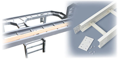
It is a structure Consisting of two LONGITUDINAL SIDE MEMBERS Connected by individual transverse members called Rung.
The Longitudinal Members are C-Channel or C Channel with the extra rib on the fold of the channel. |
| |
| FRP Cable Tray |
| |
| |
| |
Cable Tray Applications
- General Industry
- Chemical Plants
- Petrochemical Plants
- Fertilizer Plants
- Railway
- Pulp & Paper Plant
- Water / Waste Water
|
- Treatment / ETP
- Power Plants
- Marine / Ships & Docks
- Winning
- Corrosive Environment
- Coastal Areas
- OFF- Shore Installations
|
|
| |
Cable Tray Features
- Corrosion Resistant Excellent
Environmental Resistant
- Rigid & Structurally Strong
- High Impact strength
- Light Weight
- Non Conductive (Electrical & Thermal)
|
- Non Sparking
- Chemical Resistant
- Non Magnetic
- Resistant to Chipping and
Cracking
- U. V. Stabilized , UV resistant
- No Water Absorbsion
|
Cable Support Systems resist acids, salts, alkalis and a wide range of aggressive chemicals and environments which have drastic effects on galvanized steel and aluminum |
| |
| Non Conductive And Non Magnetic As cable ladder and tray is non conductive, there is no concern of transmitting electricity into the support system from damaged cables. Additionally, there is no requirement for special support conditions to prevent electrolytic corrosion. Non conductive and non magnetic features mean a safer support system.
Cable Tray Design StandaradAll cable support system components are manufactured using isophthalic polyester fire retardant resin systems that enable compliance to the VO rating of UL94, a flame spread rating of less than 25 for ASTM E-84 and a self extinguishing rating under ASTM D635.
For a more aggressive corrosion environment, a vinyl ester resin system is available to order, with equivalent fire retardant properties.
Cable Support Systems are designed to comply with the requirements of NEMA specification FG1-1986 under three load/span classifications.
CLASS A : 75kg/m on a recommended maximum span of 3.5m
CLASS B : 110kg/m on a recommended maximum span of 6.0m
CLASS C : 150kg/m on a recommended maximum span of 6.0m Ladder Cable Tray We Provide
- Solid side rail protection and system strength with smooth radius fittings and a wide selection of materials and finishes. maximum strength for long span applications
- standard widths of 6(150),12(300),18(450), 24(600), 30(750), and 36inches (900 mm)
- standard depths of 3(75 mm), 4(100mm), 5(125mm), and 6 inches (150mm)
- standard lengths of 10, 12, 20 and 24 feet
- rung spacing of 6(150mm), 9(225mm), 12(300mm), and 18 inches(450mm)
- Other tray dimension can be made to order.
|
| |
Ladder cable tray is generally used in applications with intermediate to long support spans, 12 feet(3meter) to 30 feet(5 meter).
| HEIGHT |
MATERIAL |
WIDTH |
ANGLE |
TYPE |
RADIUS |
75mm/3 inch
100 mm /4 inch
150 mm/6 inch |
Fibreglass
Polyster
Resin
or
Fibreglass
Vinyl Ester
Resin |
150 mm/6 inch
225 mm /9 inch
300 mm /12 inch
450 mm/18 inch
600 mm /24 inch
750 mm/30 inch
900 mm/36 inch |
30º
45º
60º
90º |
Horizontal Bend
Horizontal Tee
Horizontal Cross
Vertical Inside Bend
Vertical Outside Bend
Vertical Tee
Vertical Tee, Up
Right Reducer
Left Reducer
Straight Reducer
Horizontal Wye, Right
Horizontal Wye, Left |
300 mm
600 mm
900 mm
1500 mm |
Cost Performance Very favorable results have been demonstrated with our Cable Support Systems, emphasizing low installation costs, long service life and a minimum of maintenance. Very favorable results have been demonstrated with our Cable Support Systems, emphasizing low installation costs, long service life and a minimum of maintenance.
Cable Ladder And Tray Accessories
Splice Plates
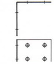
Splice Plates for Cable Tray up to 150 mm in width are 40 mm wide. For tray greater than 225 mm in width, and medium duty cable ladder, splice pates are 55 mm wide, and for heavy and extra heavy duty ladder are 100 mm wide.
 |
 |
 |
| Straight |
45° Horizontal |
Expansion |
| |
|
|
 |
 |
 |
| 90° horizontal |
45° vertical |
Adjustable Vertical |
| |
|
|
 |
 |
 |
| 30° Vertical |
30° Horizontal |
30° Horizontal |
| |
|
|
 |
 |
|
| Adjustable Horizontal |
|
|
|
|
|
|